Autonomous Drone Control & Build
Project information
- Category: Embedded Systems, Simulation
- Completion date: 10 December, 2022
- Github Repository: https://github.com/MDecarabas/ros2_px4_obstacle_avoidance
The above is my final capstone project for the Northwestern Master of robotics. The project entailed coding and building a high speed autonomous drone that is able to be controlled off board. The project had 4 Major components: Simulation, Path Planning, Building, and Testing.
Simulation
To have offboard control over the drone MavSDK together with the PX4-Autopilot software were used. To be able to test out how the drone was moving a gazebo 11 SITL Simulation was set up using the PX4 firmware. Afterwards python code was written to be able to send commands over UDP to the simulated drone, as well as receive telemetry data so that the position can be adjusted based on a path created by a global rrt path planner. To successfully build the simulation a model was needed and custom world.
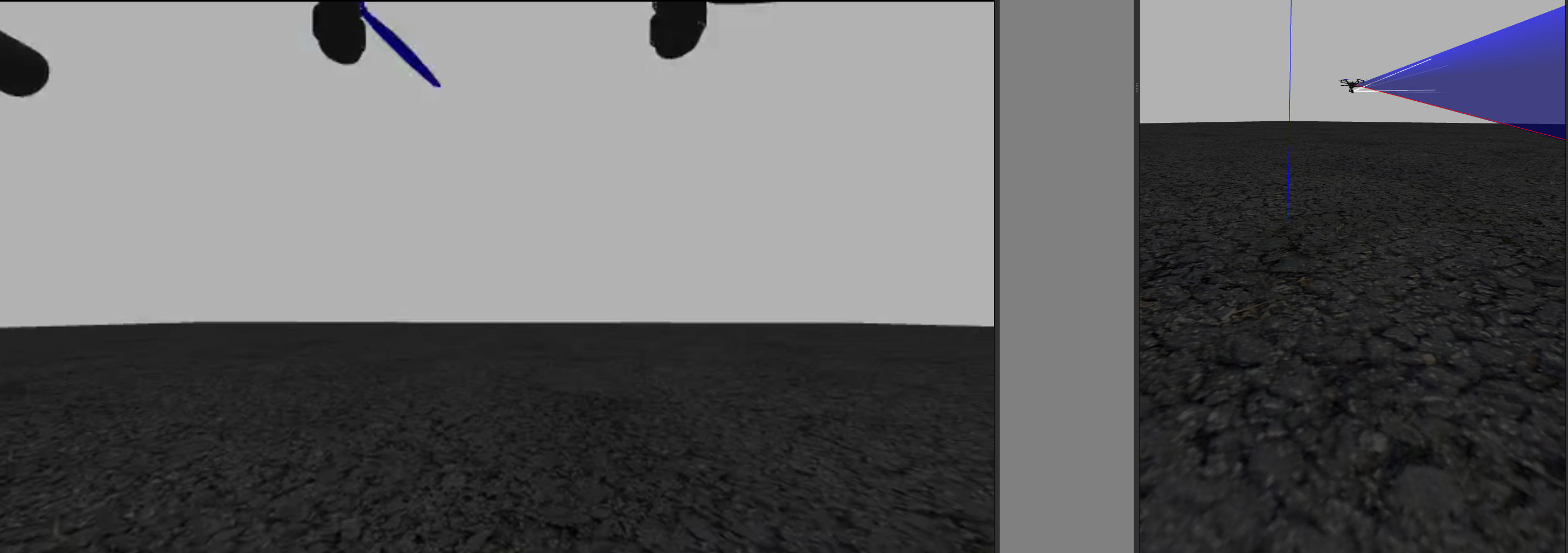
Presented above is the standard px4 drone model equipped with a realsense camera. The realsense camera was originally on a Typhoon H480 Drone and the standard drone was adapted to be able to showcase its camera feed as well as use all the sensor modalities if integrated with ROS using a plugin. The 1st image showcases a demo flight of the drone using offboard control, while the second showcases the drone viewing angle so that users may better understand what could be detected.


The second component of creating the simulation required the building of a custom world within Gazebo. The world is a maze which the drone must navigate so that it may reach the tree (the goal) using a path planner which will be explained later on. Once the world was built within gazebo the coordinates of the obstacles were stored to later be used with the global path planner.
After the model and world were created the drone using the path planner was able to successfully navigate the maze, an example of which can be seen within the gif above.
Path PlanningThe path planner chosen was an RRT global path planner. Structured as a node within the github package the path planner is a service which is called and given the parameters of the start and end goal. Within the node itself the planner is given a set of obstacles and a constrained area within which it must navigate (representative of the simulated world). Using RRT a tree branches out searching randomly across the empty space and choosing a path which has no obstacles so that it may reach the goal. Once such a path was found the service response sends a set of discretized points to be received by the drone executor node which make the drone follow the trajectory till successfully arriving at the goal. Below is a python visualizer created using the RRT algorithm implemented so that readers may get a better idea behind the proccess with which the drone arrived at the target destination.
ROS2 PX4 Integration
At the time of the code being written the suggested method by px4 to integrate with ROS2 was to use their drone communication protocol (px4_ros_com). The library was broken and as such the work around that I created was using my own custom ROS2 package that was wrapped around the python MAVSDK. The main MAVSDK function was the drone offboard control function provided which allowed for movement relative to the starting position of the drone. By setting both the drone and the RRT at a (0, 0) starting position in 2D space the drone was able to follow the trajectory given by the path planner and avoid the obstacles which were relative to it. The main node responsible for the action called a client of the RRT server to receive the waypoints that needed to be travelled. Then it followed the path till the end.
Component Selection
Due to desiring to extract the highest amount of performance from the drone the components picked had 2 main considerations, being as light as possible and providing the most power. Below were the components chosen to do so:
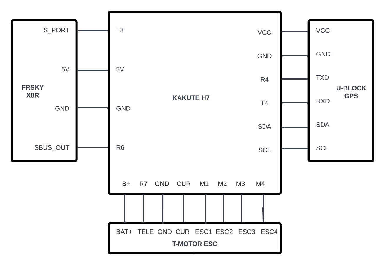
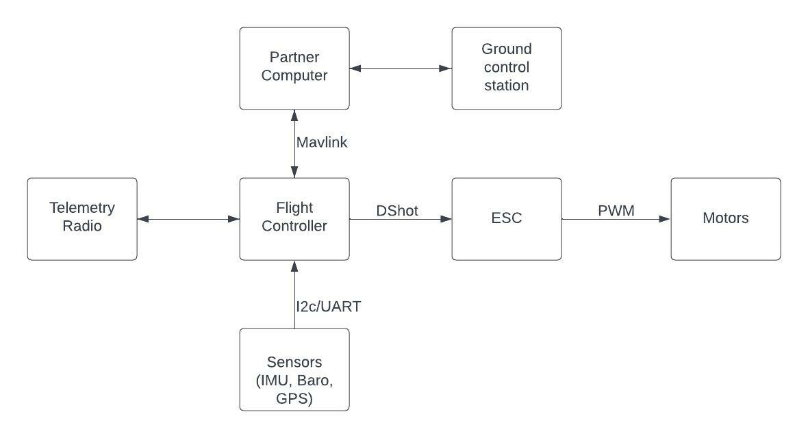
Circuit & Block Diagram
Below are the circuit and block diagram to better understand how the drone was connected both electronically to different component, as well as to allow readers to see which communication protocols were used to talk between different components and in which direction communication occured.
Testing
Due to the power of the drone and not wanting the components to be damaged during testing a special rig was designed to allow for the drone to have a full range of motion (except for altitude control). The goal was to create a safe PID tuning and testing environment while ensuring the least amount interferance with the drone dynamics. The structure pictured below was assembled using 80/20, 3d printed bearing holders, and lasercut acrylic.
Final Outcome & Post Mortem Analysis
Unfortunatly when the drone was mounted to the rig and being PID tuned for flight using QGroundControl a short occured which led to the drone catching on fire. Since the drone was a 5 inch quadrotor the damage took over most of the body and a post mortem analysis was hard to execute to see specifically what cause the problem. My current theory is that the main component responsible for the damage was the ESC as that had the most significant damage as seen in the images below. The setback happening end of the quarter as well as long wait time for parts led to the actual flight never being tested on the real life drone. However, hopefully given the code and the part details being available if anyone desires the drone can be rebuilt.


